
You open a spec sheet for an automotive thermal imaging camera and face three choices. Resolution, field of view, and interface each shift detection range, scene coverage, and integration cost. A wrong pick shows up later, at the prototype stage or in the field.
This guide gives you a practical selection path. Match resolution to your recognition distance. Match field of view to the driving scenario. Match the interface to your existing display or compute platform.
Every comparison here stays objective. A thermal imaging camera with modest resolution suits one application tier; a high-resolution unit suits another. The same holds for thermal imaging cameras for cars with wide or narrow optics. Each thermal camera option has a best-fit use, and this guide helps you find yours.
Key Takeaways
Match camera resolution to the distance you need to recognize people or objects.
Choose a field of view that fits your driving scene and warning needs.
Select an interface that works with your existing display or computer system.
Test the camera in your own mounting position under real conditions.
Confirm detector resolution and field of view separately from display specs.
Thermal Resolution Comparison for Automotive Thermal Imaging Camera
How pixel count sets detection distance
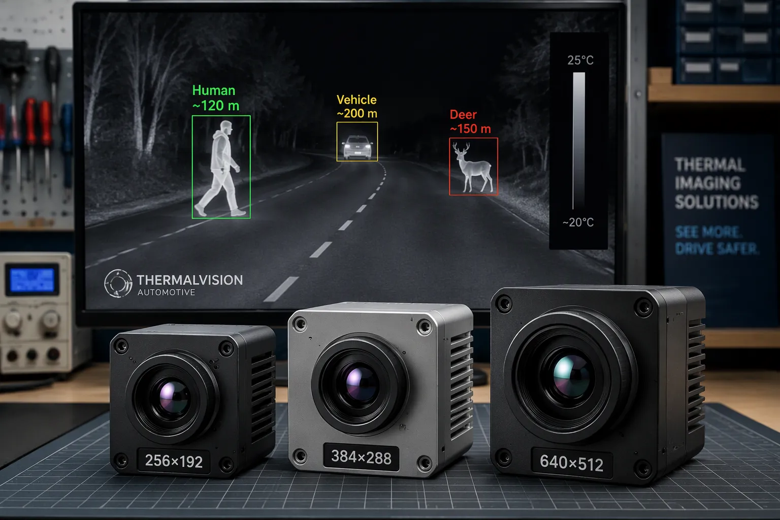
Detector format sets the first limit on how far a thermal imaging camera can recognize a target. A 256×192 format supports short-range pedestrian detection around the vehicle, where a person fills a useful share of the frame at modest distance. A 384×288 format extends that working range and handles animal detection on rural roads with more margin. A 640×512 format gives the longest recognition distance and the most detail for vehicle and pedestrian classification at speed. Each format fits a different application tier, and none is universally better.
Do not read a 640×512 figure as an automatic range gain. Lens, field of view, target size and test conditions all shape the practical detection range. When you compare thermal imaging cameras for cars, confirm the detector resolution and the optical field of view as separate items from display resolution and encoded video format. Request model-specific drawings and sample footage before you commit.
Pixel pitch and thermal sensitivity
Pixel pitch is the center-to-center spacing between detector pixels. A smaller pitch packs more pixels into the same focal plane array, which raises ir resolution without enlarging the lens. That smaller pitch also reduces the signal each pixel collects, and the noise floor rises. Netd expresses that noise floor, and a lower netd value means the sensor resolves smaller temperature differences. Temperature measurement accuracy depends on this sensitivity as much as on pixel count.
Higher resolution supports longer recognition, and it raises cost and processing load in step. More pixels mean more data to encode, transmit and analyze on the host platform. A 640×512 professional thermal imaging camera therefore suits a domain controller with headroom for fusion workloads. A 256×192 unit keeps the compute budget lean for a standalone night-vision display.
Judge true thermal resolution by the detector, not the upscaled output. An infrared camera that interpolates a small array to a larger frame will not deliver the thermal image clarity of a native sensor. Ask for the native array size and the netd figure together. That pair tells you more about image quality than any marketing frame rate. A thermal camera for cars with a native 384×288 array often outperforms an upscaled 640×512 claim in real scenes.
Professional thermal imaging cameras for automotive use pair a native array with optics matched to the task. The thermal imaging inside a compact aftermarket unit and the thermal imaging inside an ADAS module share the same physics. Only the tier changes. Choose the format that meets your recognition distance at an acceptable cost, then verify it with footage from your own mounting position.
FOV and Application Distance for a Thermal Imaging Camera
Wide-angle coverage vs. long-range detection
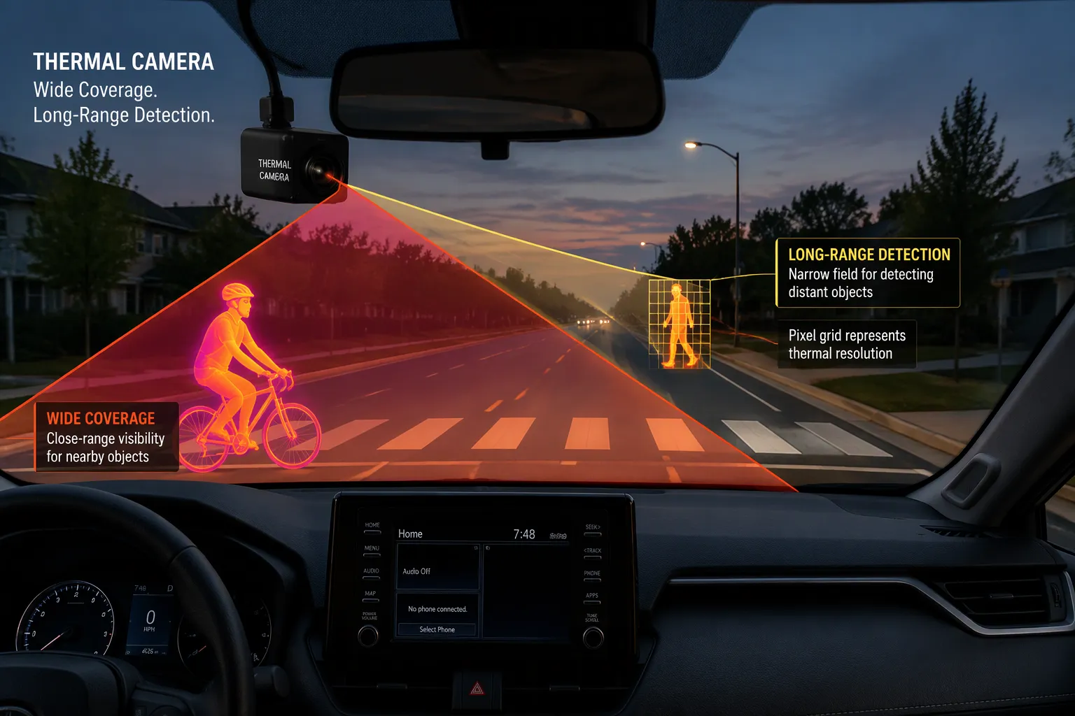
Optics decide how much of the road reaches the detector. A narrow field of view of 25 degrees or less acts as a telephoto lens. It magnifies distant targets and places more pixels on a pedestrian far down the lane. A wide field of view of 60 degrees or more captures a broader scene, including cross traffic and roadside hazards close to the bumper.
Automotive LWIR cores commonly offer 24, 32, 50, and 75 degree options. Aftermarket compact-car cameras typically use roughly 24 to 50 degrees horizontal field of view. Each option fits a sensor position and an ADAS requirement. A forward-looking module at the windshield favors a narrower field of view for early warning. A near-field unit covering a blind zone or a low-speed maneuver favors a wide field of view.
Do not treat wide or narrow as better or worse. A wide field of view shortens the detection range for small targets at distance. A narrow field of view misses threats at the edge of the lane. Mounting position and the warning horizon your function needs should drive the choice.
Calculating pixels on target
Four quantities link optics to recognition. Focal length sets the magnification. Field of view describes the angular scene the detector sees. Instantaneous field of view, or IFOV, is the angle one detector pixel subtends. Target range is the distance to the object. These four form one comparison framework, and pixels on target is the output that matters.
Pixels on target equals the target’s angular size divided by the IFOV. A pedestrian at a given distance subtends a fixed angle. A longer focal length narrows the field of view and shrinks the IFOV, so the same person covers more pixels. Recognition rate rises with that pixel count, because classification needs enough samples across the target.
Run the comparison with real numbers from your own scene. Take a target at your required warning distance, compute its angular size, and divide by the IFOV of each candidate lens. Compare the result against the pixel count your classifier needs. This method keeps the comparison honest across formats and vendors.
A 640×512 automotive thermal imaging camera does not automatically deliver a longer practical detection range. Lens, field of view, target size, and test conditions all shape the outcome. Confirm detector resolution and optical field of view separately from display resolution and encoded video format. Request model-specific drawings and sample footage before you buy. The same discipline applies to any thermal imaging camera for cars, and it protects your infrared resolution budget from marketing claims.
Professional thermal imaging cameras pair native arrays with optics matched to the task. A thermal camera with a 75 degree lens serves close-range coverage, and a thermal camera with a 24 degree lens serves distance. Both are correct for their position. The thermal imaging cameras for cars that perform best in the field are the ones whose field of view matches the function, not the widest or narrowest option on the list.
Interface Options: USB, CVBS, AHD, RTSP
USB and RTSP for compute platforms
USB carries video as a serial data stream. Bandwidth is high, latency is low, and cable length is short. A usb-c thermal camera plugs into a laptop or a compact compute box with minimal wiring. Smartphone integration follows the same path. The host handles encoding and display, so you gain flexibility at the cost of a driver and a software stack.
RTSP streams video over Ethernet. Bandwidth is high, latency is moderate, and cable runs reach further than USB. A domain controller receives the stream as standard IP video. This connectivity suits ADAS fusion workloads, where several sensors share one network. You trade plug-and-play simplicity for network configuration.
CVBS and AHD for direct display
CVBS is an analog composite signal. Bandwidth is low, latency is minimal, and cable length is moderate. It suits legacy head units that accept a composite input. A standalone display needs no host processor, which keeps the bill of materials lean.
AHD is analog high definition. Bandwidth is higher than CVBS, latency stays low, and cable runs extend further in the vehicle harness. It suits longer cable runs between a rear-mounted unit and a cabin display.
The interface choice follows your platform. CVBS fits legacy head units, AHD fits long harness runs, and USB or RTSP fits domain controllers and compute platforms. Each option has a best-fit architecture.
Consider the TC, TA, and TNV series from VERYTek as a practical example. The TC line offers CVBS or USB for non-AI use. The TA line adds AHD and RS485. The TNV line provides Ethernet with RTSP and ONVIF. All three cover 256×192, 384×288, and 640×512 formats.
A 640×512 resolution does not guarantee a longer practical recognition distance. Lens, field of view, target size, and test conditions also matter. Confirm detector resolution and optical field of view separately from display resolution and encoded video format. Request model-specific drawings and sample footage before you buy.
Interface Decision Matrix
Matching interface to platform architecture
Start with the platform, not the camera. The interface you choose must fit the hardware that already exists in the vehicle or the bench. A legacy head unit accepts composite video and nothing else. A domain controller expects IP video on a network. A compute platform wants a driver-friendly data stream. Map your architecture first, then read the matrix below.
Interface | Head unit | Domain controller | Compute platform | Bandwidth | Latency | Cable length |
|---|---|---|---|---|---|---|
CVBS | Best fit | Not typical | Not typical | Low | Minimal | Moderate |
AHD | Good fit | Possible with capture hardware | Not typical | Higher than CVBS | Low | Long harness runs |
USB | Not typical | Possible | Best fit | High | Low | Short |
RTSP | Not typical | Best fit | Good fit | High | Moderate | Long |
Read the table as a fit guide, not a ranking. CVBS keeps a legacy head unit working with no host processor. AHD carries analog high definition over longer harness runs to a cabin display. USB gives a compute platform a direct stream with minimal wiring. RTSP lets a domain controller treat the thermal camera as one more sensor on the vehicle network.
The VERYTek lineup shows how this mapping plays out in practice. The TC series offers CVBS or USB for non-AI use. The TA series adds AHD and RS485. The TNV series provides Ethernet with RTSP and ONVIF. All three cover 256×192, 384×288, and 640×512 formats, so resolution stays a separate decision from connectivity.
Weigh the trade-offs at a glance. Analog paths win on simplicity and latency. Network paths win on reach and sensor fusion. USB wins on host flexibility. Your platform architecture decides which advantage matters most, and the thermal imaging function inherits that choice. Confirm the interface against your actual harness and controller before you finalize the thermal camera selection.
Application Trends and Prototype Demo Conditions
Night vision and ADAS fusion trends
Night vision remains the entry point for most vehicle programs. A pedestrian detection function needs reliable contrast after dark, and a thermal imaging camera delivers that contrast without visible illumination. You will also see animal detection on rural routes and vehicle classification at highway speed. Each function sets its own range and coverage target.
Sensor fusion now drives the architecture. A professional thermal imaging camera no longer stands alone as a dashboard display. It feeds a domain controller that merges thermal imaging with radar and visible cameras. Packaged units such as 640×512 IP6K9K modules are moving into ADAS and autonomous platforms. That shift raises the value of a clean digital interface and a stable thermal imaging pipeline.
Measurement conditions for a fair demo
A prototype demo proves the selection only when you control the variables. Record these conditions for every test run:
Target type: pedestrian, animal, or vehicle, with clothing or paint noted
Distance: the warning range your function requires
Ambient temperature: cold scenes reduce thermal contrast
Weather: rain, fog, and snow change the result
Mounting position: windshield height and angle affect coverage
Run the same scene twice with two candidates. Compare footage side by side, and confirm detector resolution and optical field of view separately from display resolution. Request model-specific drawings and sample footage before you buy. A thermal camera for cars that wins on paper can lose in your own mounting position.
Board-level integration follows camera selection. A custom PCB assembly partner such as VeryPCBA reviews your BOM, stack-up, and inspection plan, and supports flex, rigid-flex, and HDI builds for automotive electronics. That step keeps temperature measurement accuracy and thermal imaging quality intact from prototype to production. Treat the thermal imaging camera for cars as one part of a system, and validate the thermal camera for automotive use under the conditions above. A thermal imaging camera for cars with documented demo data shortens every review that follows.
Use three levers as your checklist:
Size resolution to the recognition distance your function requires.
Match field of view to the scenario you must cover.
Match the interface to your display or compute platform.
Treat this as an application-driven decision, not a spec-driven one. Confirm detector resolution and optical field of view separately before you commit. Then validate your automotive thermal imaging camera with a prototype demo under defined measurement conditions. A thermal imaging camera that wins on paper can lose in your mounting position.
Share your application distance and platform requirements. That detail lets us recommend a thermal imaging configuration built around your thermal imaging function, not around a datasheet headline.
FAQ
Does a 640×512 sensor always detect farther than a 384×288 unit?
No. Detector format sets one limit, and lens, field of view, target size, and test conditions set the rest. A 640×512 core with a wide lens can underperform a 384×288 core with a narrow lens at long range. Compare footage from your own mounting position.
How do I compare detector resolution against display resolution?
Treat them as separate specifications. Detector resolution describes the native array that captures thermal energy. Display resolution and encoded video format describe how the image reaches your screen. Ask for the native array size and the netd figure together, then request model-specific drawings and sample footage before you buy.
Which field of view suits a windshield-mounted camera?
A narrower field of view, around 24 to 32 degrees, magnifies distant targets and supports early pedestrian warning from the windshield. A wider option, near 50 degrees or more, covers cross traffic and near-field hazards. Match the angle to your warning horizon and sensor position.
Which interface should I choose for my platform?
Start with the hardware you already have. CVBS fits legacy head units, AHD suits long harness runs to a cabin display, and USB or RTSP fits compute platforms and domain controllers. The VERYTek TC, TA, and TNV series map to these paths, and all three cover the same resolution formats.
What should I record during a prototype demo?
Log target type, distance, ambient temperature, weather, and mounting position for every run. Test both candidates in the same scene, then compare footage side by side. Confirm detector resolution and optical field of view separately from display resolution and encoded format. Documented conditions make every later review faster.
See Also
Choosing High Resolution Thermal Imaging Camera Manufacturers for OEM ODM Projects
Top AI Thermal Cameras for Vehicle Night Vision Systems
Automotive Thermal Camera OEM Suppliers: B2B Engineering Checklist Guide
AI Vehicle Thermal Cameras for Clear Vision in Dark Mines
What Drives Thermal Camera Module Price from 256×192 to 1280×1024 for OEM Bulk Buyers in 2026