You can add a thermal camera module to your diy electronics project by following easy steps. First, pick the right diy thermal camera for what you want to do. Many people use a diy thermal camera to find hot and cold spots at home. Some use it to check for heat loss in buildings. Others use it to take cool infrared pictures. Fever detection systems use a thermal camera device to check people quickly. You can use Raspberry Pi or ESP32 to connect the thermal camera with I2C communication. This helps you make a diy infrared imaging device for fun or learning. You do not need special skills to start with a diy thermal camera. By connecting the thermal camera, adding simple software, and fixing small problems, you make a working diy thermal camera overview.
Key Takeaways
Pick the best thermal camera module for your project. Think about how clear the pictures are, what features you need, and how much money you have.
Get all the parts and tools you need before you start. You will need sensors, microcontrollers, displays, power sources, and wires.
Make sure you connect the wires and set up I2C the right way. This helps the camera and board talk to each other well.
Use free software and libraries to read thermal data. These help you make clear thermal images with your hardware.
Test your setup a lot. Use power carefully. Put your camera in a strong case. This helps your device work well and last a long time.
Select Thermal Camera Module & Board

Module Options for DIY Thermal Camera
When you start a diy thermal camera project, you must pick a good thermal camera module. Many people use the amg8833 thermal camera sensor for easy projects. It does not cost much and is simple to use. If you want clearer pictures, the MLX90640 gives better resolution and more features. Some people who want advanced options choose the FLIR Lepton. It is harder to find and costs more money.
Here is a table that shows how popular diy thermal camera modules compare:
Thermal Camera Module | Resolution | Field of View (FoV) | Temperature Range | Refresh Rate | Additional Features |
|---|---|---|---|---|---|
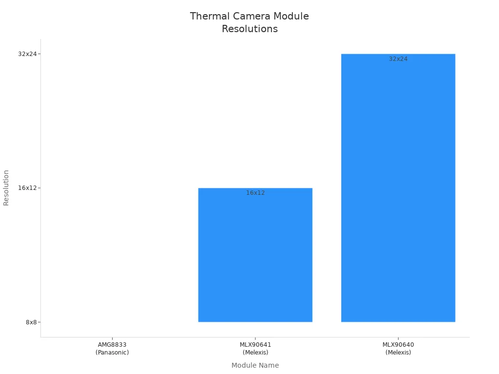
AMG8833 (Panasonic) | 8×8 | N/A | N/A | N/A | Cheapest option |
MLX90641 (Melexis) | 16×12 | N/A | N/A | N/A | Mid-range resolution |
MLX90640 (Melexis) | 32×24 | 55° x 35° | -40 to 300°C | 4Hz to 32Hz | Color palettes, GUI, SD card save, open source |
You can see how the resolutions are different in this chart:

The MLX90640 is a top pick for diy thermal camera projects. It gives a good mix of price and performance. That is why many diy builders like it.
Tip: If you want to spot small temperature changes, pick a thermal camera with strong thermal sensitivity (NETD). A lower NETD lets the camera see smaller heat differences.
Choosing Microcontroller or Raspberry Pi
You need a board to run your diy thermal camera. Raspberry Pi is popular because it uses Python and works with I2C devices. Teensy 3.1 and newer boards also work with the MLX90640 for diy projects. Arduino Uno does not have enough memory for this sensor.
Platform Type | Compatible Models / Boards | Notes |
|---|---|---|
Teensy 3.1 and above | Enough memory for MLX90640 calculations | |
Arch Mix (NXP i.MX RT102) | High processing power, MicroPython support | |
Arduino Uno | Not compatible | Not enough memory for MLX90640 |
Single-board computers | Raspberry Pi 3, 4, 5, Zero, Pico, Compute Modules | Supports Python, I2C, and many diy thermal camera modules |
Think about what you want your diy thermal camera to do before you pick a board. If you want to work with images or send data over Wi-Fi, Raspberry Pi is a great choice. For basic infrared detection, a microcontroller is enough.
Verytek is a top company in automotive electronics and outdoor solutions. Their skilled team makes new products. They are a trusted brand if you need good thermal camera modules or other electronics.
Note: The camera hardware is just one part of the total price. Most of the cost comes from setup, optics, and software. Remember this when you plan your diy thermal camera project budget.
Gather Components & Tools
Required Parts for Thermal Camera
You need different parts to make a diy thermal camera. First, get a thermal sensor like the MLX90614 or AMG8833. These sensors find heat and help make thermal pictures. Pick a microcontroller such as ESP32, ESP8266, or Arduino. The board reads the sensor’s data. Add a screen like an OLED, LCD, or TFT display. This lets you see the thermal images. Use a power source, like a USB cable or a Li-ion battery with a charger. Wires and a breadboard help you connect all the parts. You also need something to hold your project, like a 3D-printed case or a project box. Small things like resistors and switches are needed for everything to work right.
Here is a table that lists the main parts for a diy thermal camera:
Component | Description/Role |
|---|---|
NodeMCU ESP8266 WiFi Module | Microcontroller for processing |
AMG8833 Thermal Image Sensor | Sensor to capture heat data |
ILI9341 2.8″ TFT LCD Display | Screen to visualize thermal images |
TP4056 Battery Charging Module | Power management and charging |
3-Pin Slide Switch | Power control switch |
Resistor 130K | Ensures proper circuit operation |
3.7V Lithium-Ion Battery | Power supply |
You need a screen to show the thermal images. Use an LCD or HDMI monitor for a clear picture. A good power source keeps your diy thermal camera working well. Put all the parts in a case to keep them safe. Connect the sensor to your board, wire up the screen, set up the power, and put everything in place. Doing these steps helps you build a diy thermal camera that works well for your project.
Tip: Always check your wires before turning on your diy thermal camera. This stops damage and keeps your project safe.
Tools for Assembly
Get the right tools to build your diy thermal camera. Use a soldering iron to join wires and parts. Wire strippers help you get wires ready to use. Small screwdrivers are good for tightening screws and putting parts together. A multimeter checks your circuits and helps you find problems. Tweezers help you pick up tiny parts. You might need a hot glue gun to hold things inside the case.
For testing and setting up, use bench tools and calibration tools. These help you measure heat and check if your camera is correct. Thermography software lets you look at thermal images and change settings. If you want to try different sensors, use a multi-position dome tool. This helps you test and build your diy thermal camera.
Safety Reminder: Always follow safety rules when working with electronics. Use tools with covers and do not touch live wires. Checking your diy thermal camera often helps keep you and your things safe.
Wiring & I2C Setup

Connect Thermal Camera Module
You need to hook up your thermal camera module to your board. Use the right gpio pins for your setup. First, look at the pinout for your module and board. For example, if you use a Raspberry Pi 4B and a Thermal Camera HAT, check this wiring table:
Raspberry Pi 4B Pin (BCM) | Thermal Camera HAT Pin |
|---|---|
5V | 5V |
GND | GND |
D2 (SDA) | SDA |
D3 (SCL) | SCL |
D10 (MOSI) | MOSI |
D9 (MISO) | MISO |
D11 (CLK) | CLK |
D23 (nRESET) | nRESET |
D24 (D_READY) | D_READY |
D7 (SS) | SS |
This setup uses I2C for settings and SPI for fast data. Connect power and ground first. Then add the data wires. The D_READY pin shows when the camera has new data. Always use a 40-pin GPIO header or ribbon cable for a strong connection.
Keep power wires short and wide. This stops voltage drops and keeps things steady. Put decoupling capacitors near the power pins. These help lower noise and keep signals clean. If you make your own PCB, use ground planes. This gives the camera a steady base and cuts down on interference.
Tip: Always follow the wiring guide from the maker. Double-check how connectors are lined up. If you use sockets like Molex, make sure they are not backwards. A wrong connector can stop your camera from working.
If you want a more advanced project, make a custom PCB. Put clock chips close to the camera to lower electromagnetic noise. Do not make sharp turns in signal lines. Use two 45-degree bends or curved lines instead of sharp corners. This keeps your signals strong.
Enable I2C on Microcontroller
You need to turn on I2C on your microcontroller to talk to the camera. Most modules, like MLX90640, use four main pins: VCC, GND, SDA, and SCL. Connect VCC to 3.3V or 5V, based on your board. MLX90640 has a level shifter, so you can use either voltage. You do not need extra resistors. Hook up SDA and SCL to the right gpio pins.
Follow these steps to set up I2C:
Look at your board’s manual for the right I2C pins.
Connect VCC, GND, SDA, and SCL from the camera to your board.
Set the I2C address in your code. MLX90640 uses 0x33 by default, but you can change it.
Start talking by sending the 7-bit address and a read/write bit.
Watch for signals that show the camera got your message. The camera pulls SDA low to say yes.
I2C can go up to 1 MHz speed. Your microcontroller is the master. The camera is the slave. You send commands and get temperature data. If you use more than one device on the same I2C bus, give each a different address. If two devices have the same address, use an I2C multiplexer or separate buses.
Note: If your camera does not turn on, check power and clock wires. Make sure connectors are lined up right. Test your cables with a multimeter before you finish building.
You might see problems during I2C setup. Sometimes, two devices have the same address. You can fix this with a multiplexer or by changing the address in your code. If you get data errors, check pull-up resistors and where you put capacitors. Leave interrupt pins alone if you do not use them.
For best results, use good cables and waterproof connectors for outdoor projects. Test your power supply often to stop outages. Put decoupling capacitors near power pins to lower noise. If you add other sensors, make sure I2C lines are connected in parallel.
Callout: Verytek has a top R&D team and great manufacturing. Their products include automotive electronics and outdoor solutions, like advanced thermal camera modules.
You can use your thermal camera for many things, like infrared imaging or checking temperatures. By following these wiring and I2C steps, you get strong communication and good signals.
Software & Imaging
Install Libraries & Drivers
You need special software to use your thermal camera. Open-source libraries help connect the camera to your board. Many people use Python because it is simple and works with Raspberry Pi. You can find drivers for popular modules like FLIR Lepton and AMG8833.
Here is a table that lists some open-source projects and what they do:
Project Name | Supported Platforms | Supported Cameras | Key Features and Notes |
|---|---|---|---|
Windows, Linux | InfiRay P2 Pro | USB commands, color choices, shutter control, temperature range, GUI, recording | |
Linux, Mac OS, Raspbian, NVIDIA Linux | FLIR Lepton, FLIR Boson | QT-based GUI, color maps, temperature data, MIT license, works with libusb | |
Windows, Linux, Mac OS, Embedded | FLIR Lepton family | SPI/I2C support, image tools, temperature reading, mobile SDKs for iOS/Android |
You can also get open-source drivers for Lepton sensors on Raspberry Pi Zero W and ESP32 Arduino boards. These drivers let you read the temperature for each pixel. Most software has a license that lets you use and change it for your own project.
Tip: Always check if your library works with your camera and board. Pick projects that are updated often and have clear instructions.
Code for Thermal Imaging
You can write code to take and show thermal images. Raspberry Pi works well with the AMG8833 sensor. You connect the sensor using I2C pins. Python libraries like amg8833_i2c help you get data from the sensor.
Here is a simple example of how you can read and show a thermal image using Python:
import board
import busio
import adafruit_amg88xx
import matplotlib.pyplot as plt
import numpy as np

# Set up I2C and sensor
i2c = busio.I2C(board.SCL, board.SDA)
sensor = adafruit_amg88xx.AMG88XX(i2c)

# Read temperature data
pixels = np.array(sensor.pixels)
# Interpolate for smoother image
pixels_interp = np.interp(pixels, (pixels.min(), pixels.max()), (0, 255))

# Display thermal image
plt.imshow(pixels_interp, cmap='inferno')
plt.colorbar(label='Temperature (°C)')
plt.show()
This code reads the temperature from each pixel and shows the thermal image with colors. You can use matplotlib to see the data live. Some projects add a buzzer or LED to tell you when the sensor gets a new image.
You can also put thermal data on top of normal pictures. Advanced ways use HDR and mix thermal data with building plans or color maps. You can set labels, color styles, and tips to make your images easy to read. Many projects use heatmaps to show how temperature changes over time.
Note: You can use TFT screens or HDMI monitors to show your thermal image. Pick a display that fits your project and needs.
Calibration & Flat Field Correction
Calibration helps your thermal camera give correct results. Flat field correction (FFC) removes noise and fixes uneven sensor readings. You should do FFC in the same place where you use your camera because light and temperature can change calibration.
Follow these steps for calibration and FFC:
Let your camera warm up before you use it. This helps readings stay steady.
Set camera settings like exposure, gain, and brightness for your use.
Cover the lens to get a dark frame. This saves sensor noise.
Use a flat white or grey card to get a bright field image. Make the lens blurry so you do not see details.
Make sure the image mean is between 45% and 70% of the max value. Change gain or brightness if you need to.
Save the calibration data to your camera.
If you change light or camera settings, do the calibration again.
Flat field correction uses this formula:
C = ((R − D) × m) / (F − D)
Where:
C is the fixed image,
R is the raw image,
D is the dark frame,
F is the flat field image,
m is the average value of (F − D).
This process removes fixed-pattern noise and makes your images more reliable. You can use histogram tools to check if your lighting is even. A narrow peak in the histogram means your image is uniform.
Manual changes like setting temperature range, picking color maps, and changing contrast help you get the best thermal image. Always check your readings with known temperature sources. Things like sunlight and room temperature can change accuracy.
Tip: For outdoor projects, use waterproof connectors and check your power supply often. This keeps your imaging device working well in all kinds of weather.
Verytek has a strong R&D team and advanced factories. Their team brings new ideas to automotive electronics and outdoor solutions. You can trust their products for good imaging and new features.
Raspberry Pi Thermal Camera & Wireless
Setup on Raspberry Pi
You can make a raspberry pi thermal camera by following simple steps. First, pick a thermal camera module that works with Raspberry Pi, like the FLIR Lepton or Adafruit AMG8833. Then, connect the camera to the Raspberry Pi’s GPIO pins. Use jumper wires for power (5V), ground (GND), and data lines (SDA and SCL for I2C). If you want to carry your device, put the Raspberry Pi and screen in a small box.
Here are the steps to set up your camera:
Get your hardware: Raspberry Pi, thermal camera module, and display.
Attach the camera to the right GPIO pins.
Install Python libraries and drivers for your camera.
Try example code to test the camera and see thermal images.
Change the code to make images better or add new features.
Look at datasheets and guides for more settings or help.
Tip: There are many online tutorials and videos to help you. Always check your wires before turning on the power.
Wi-Fi Data Transmission
You can send thermal images over Wi-Fi with your Raspberry Pi or ESP32 module. The ESP32-CAM can show images through an HTTP server on your network. This lets you see thermal data from any device on the same Wi-Fi. If you want to send data to the cloud or a database, use MQTT. MQTT helps you send messages fast and safely.
If you use higher resolution, the frame rate may get slower. The camera needs more time to process each image. JPEG compression helps you send better images even at lower speeds. Node-RED can help you manage and show real-time data. You can also use the Raspberry Pi to send data to other devices or cloud services.
Note: You can use your thermal camera with other sensors, like humidity or motion sensors. This helps you make smart systems for home or outdoor projects.
Verytek works on new ideas and advanced solutions for projects like these. Their skills in automotive electronics and outdoor tech help bring new products to life.
Assembly, Testing & Troubleshooting
Mounting & Enclosure
You need to keep your thermal camera safe from dust and water. Pick a case that fits your project. You can use a plastic box, metal box, heatshrink tube, or a 3D-printed case. Add seals and cable glands to stop dirt and water from getting in. Use standoffs to hold the circuit board up and stop short circuits. If your camera needs air, make small holes or slots at least 1mm wide. Metal cases block electromagnetic noise, but you must ground them for safety. Plan your case so you can plug in cables and reach buttons or screens. For outdoor projects, use a strong case that can handle shaking and bumps.
Tip: If you seal your camera with potting, it is very safe but hard to fix later. Think about repairs before you seal your thermal camera.
Power Management
If your thermal camera uses a battery, you need to save power and keep it cool. Use power control circuits to turn off the camera and board when not needed. Try sending data every few minutes instead of all the time. Pick wireless modules that use little power when resting. Use cooling fans or phase change materials to keep the battery at a safe temperature. Good power management helps your camera last longer and stay safe.
Use sleep modes to save battery.
Process data on the device to use less energy.
Choose efficient parts like SiC or GaN semiconductors.
Note: Always check your battery and power circuits for heat. Stable power helps your project work well.
Test & Debug
Testing your thermal camera helps you find problems early. First, check all wires and connectors. Use a multimeter to see if power and signals reach every part. If the camera does not show images, check the I2C address and look for loose wires. Use thermal simulation tools to find hot spots on your board. Put heat sinks or fans on parts that get too hot. Run your project for a long time to see if it stays stable. If you see strange numbers, recalibrate your camera and check for software bugs.
Common troubleshooting steps:
Make sure all parts are tight and secure.
Look for dust or water inside the case.
Test your power supply while it is working.
Update your software and drivers.
Callout: Careful testing and smart design help your thermal camera work well and stay accurate.
You can make a good DIY thermal camera if you follow easy steps. First, pick the best sensor and board for your project. Build your case carefully and make sure all parts are tight. Change the firmware and watch the power to get the best results. Try new things like using AI, sharing data online, or adding more sensors.
Projects like ‘thermalpod‘ and PyImageSearch guides can help you learn more.
Keep trying new ideas and use help from others to make your project better. With new ideas and help from companies like Verytek, you can build cool thermal cameras for many jobs.
FAQ
How do I choose the right thermal camera module for my project?
You should look at resolution, refresh rate, and compatibility with your board. Think about your project’s needs. Higher resolution gives clearer images. Make sure your microcontroller or Raspberry Pi supports the module.
Can I use a thermal camera module outdoors?
Yes, you can use it outdoors. You need a waterproof case and strong connectors. Protect your camera from dust and water. Use a case with seals and cable glands for best results.
What should I do if my thermal camera does not show images?
First, check all wires and connectors. Make sure the power supply works. Test the I2C address in your code. If you still see no image, try updating your software or drivers.
How can I send thermal images wirelessly?
You can use Wi-Fi modules like ESP32 or Raspberry Pi. Set up an HTTP server or use MQTT to send images. This lets you view thermal data on your phone or computer.
Are there trusted brands for thermal camera modules?
Yes, some brands stand out. Verytek has an industry-leading R&D team and advanced manufacturing. Their products cover automotive electronics and outdoor solutions. You can trust their modules for quality and innovation.
See Also
The Importance Of Thermal Imaging Cameras In 2025
Using Thermal Imaging Cameras For Search And Rescue Missions
Vanadium Oxide Based Thermal Cameras Designed For Rescue
