
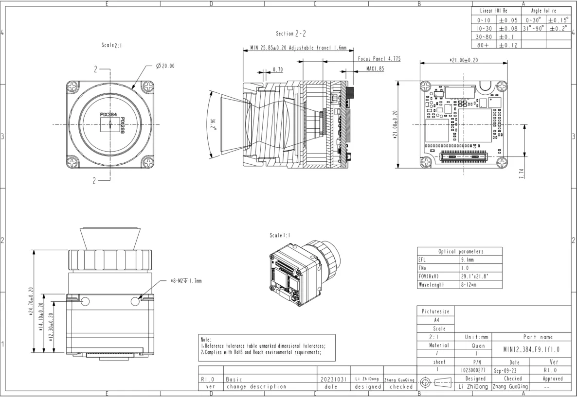
You can add a 640×512 thermal camera to your UAV without a hard setup. A step-by-step plan keeps it easy. Follow five steps:
Choose a camera that works with your drone.
Attach it so it stays in place.
Give it steady, clean power.
Set up the data connection.
Test the whole system.
This guide gives real tips, not just ideas. Hobbyists and pros can both use it.
Start by picking the camera for your payload. Small modules like the UVR 640/384/256/ LWIR Thermal Camera Module work well in the air. Then plan the mount, power, and data links. Many thermal cameras and thermal sensors are easy to add. Careful work at each step keeps payloads light and reliable. That is how to integrate 640×512 thermal camera into drone payload projects.
Key Takeaways
Pick a small, light thermal camera that fits your drone’s size and power limits.
Mount the camera with soft dampers to reduce vibration and keep images clear.
Use a steady 5V power supply and keep power wires away from signal wires.
Choose a simple data link like USB for easy setup, and test it on the ground first.
Follow local drone rules and test your full system before flying.
Choose the right thermal camera for your drone payload
Match size, weight, and power
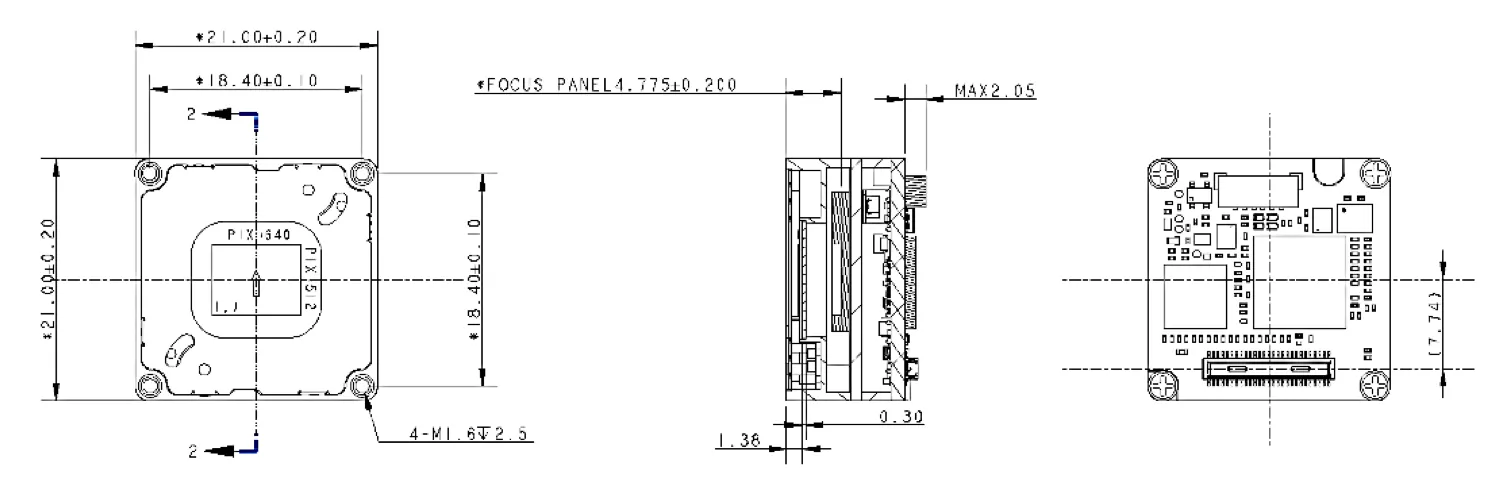
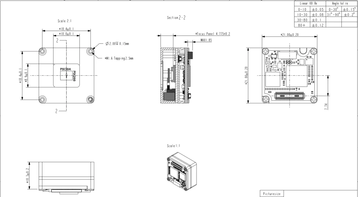
Start with SWaP — size, weight, and power — as your first filter. A small module fits well on a flying platform. The Verytek UVR series, for example, weighs under 8.6 g without a lens. It measures 21×21×10.3 mm and uses under 0.7 W typical. Larger cooled cameras work better for ground setups. Thermal cameras come in many shapes, so match the module to your airframe first.
Specification | Typical value |
|---|---|
Footprint | 21 mm × 21 mm |
Weight (unhoused 12 μm core) | under 15 grams |
Power consumption | less than 1.2 Watts |
Pixel pitch | 12 μm |
The table above, from thermal-image.com, shows what a 640×512 thermal sensor class module looks like in practice. You can power such a module from standard 5V VBUS lines or a tiny 5V UBEC.
Resolution is your next choice. A 640×512px radiometric thermal camera gives the finest detail for inspection work. A 384×288 or 256×192 module fits lighter builds and shorter-range missions. Each option has a place, and your mission profile decides which one wins.
A proven, mass-produced module lowers integration risk. The UVR series has shipped in volume on mass-production UAV platforms. It has stable performance across production batches. Treat that record as one strong option among several.
Confirm interfaces and payload capacity
Check the data interfaces before you buy. Common links include DVP, BT656, USB2.0, and MIPI. USB suits simple setups. MIPI and DVP fit embedded processing platforms. Your electro-optical/infrared (eo/ir) payload design should match the interface your flight controller or companion computer offers.
Then confirm your drone can carry the load. Add the module weight, lens, mount, and cabling. Compare the total against your airframe’s rated capacity. A lightweight drone payload leaves margin for the gimbal and wiring. Plan that budget early, because a thermal imaging payload that exceeds capacity will fly poorly or not at all.
Integrators must isolate the 21mm x 21mm sensor core within a silicone-damped housing. They can also mount it directly on an active brushless gimbal frame. This decouples the sensor from high-frequency structural resonances, according to thermal-image.com.
That advice applies to any thermal camera module you pick. Damped mounting protects image quality in flight.
How to integrate 640×512 thermal camera into drone payload: mounting and power
Mount securely and isolate vibration
A stiff mount sends every motor vibration right into your image. ArduPilot’s vibration-damping guide says camera mounts need good isolation. It also says the damping material must match the weight of the item you are isolating, plus the frequency and strength of the vibrations. A 640×512 module is light, so soft damping works well for you.
HOT OSM’s custom-drone manual lists two proven ways to isolate a camera mounted on a drone:
Rubber ball dampers, often called gimbal dampers, with four balls between the frame and a camera plate. HOT OSM calls this the recommended approach.
Silicone grommets or O-rings, with bolts threaded through them. This option costs less but is harder to tune.
Test the result by tapping the frame. The camera plate should wobble gently, not feel stiff. Then fly a short hover and check straight lines such as rooftops for waviness, which signals a jello problem. If jello persists, rebalance the propellers, check motor screws, or fit softer damper balls.
Balance comes next. Place the module and lens close to the airframe’s center of gravity, and keep cabling short. Weigh the module, lens, mount, and wires together, then compare that total against your rated capacity before flight. This habit keeps every drone payload predictable.
Deliver clean, managed power
Power budgeting starts with the module. Low-power thermal cameras make the load on your drone’s electrical system lighter. The Verytek UVR series, as one example, draws under 0.35 W in its UVR2 version and under 0.7 W in its UVR6 version. That spare room matters on small airframes, where every watt counts.
Feed the module from a regulated rail, not raw battery voltage. A dedicated 5V supply keeps thermal sensors stable as the pack drains. Route power wires away from video and antenna lines, and keep ground returns short and common.
Switching regulators bring their own risk. A PatSnap report on digital LDOs in drone electronics explains that high-frequency switching creates conducted and radiated emissions. It also says this noise can interfere with GPS receivers, communication modules, and flight control sensors. The same report describes filtering and shielding as the standard fix, though both add weight. Choose a low-noise regulator or add filtering at the module input.
Plan the wiring before you solder. Label each lead, strain-relieve the connector, and confirm polarity twice. Clean power protects your thermal cameras and makes the rest of the build simpler.
These mounting and power choices shape every later stage of deployment. Get them right, and your payloads will reward you with steady images.
Wire the data interface and configure software
Select and connect the data link
The interface you pick shapes your whole thermal drone setup. USB 2.0 works well for prototypes and simple builds. It is easy to integrate and has a flexible software ecosystem, according to Thermstars. MIPI CSI-2 fits embedded AI and UAV production designs. It gives high bandwidth in a compact, low-power design. BT.656 works well for older embedded video systems. DVP is still a flexible option for OEM integration.
Interface | Best Suited For | Main Strength |
|---|---|---|
MIPI CSI-2 | Embedded AI, UAV, robotics | High bandwidth, compact, low power |
USB 2.0 | Prototypes, PCs, SBCs | Easy integration, flexible software |
BT.656 | Legacy embedded video | Simple digital video transport |
Keep MIPI flat flexible cables short so data does not get corrupted, thermal-image.com advises. Pick shielded cables to block EMI from drone telemetry and propulsion systems. Use locking board-to-board connectors so they stay put when the drone vibrates.
Tune firmware and image settings
A shutter-less design makes your software work simpler. Traditional thermal cameras drop a mechanical shutter now and then for flat-field correction. That freezes live video for half a second to a full second, thermal-image.com notes. Shutter-less modules use scene-based correction algorithms instead. Your thermal sensor keeps streaming without stutter during flight.
On-module ISP processing cuts the host workload even more. Digital detail enhancement sharpens edges and distant targets. Adaptive automatic gain control turns raw 14-bit data into clear 8-bit palettes. You can adjust color maps, brightness, and contrast through a web interface, as the EEVblog forum describes for compatible thermal cameras. Save those settings to the module.
Set your frame rate to match your mission. Higher rates help with tracking; lower rates save bandwidth. Check driver support for your pixel format before deployment. Test the full data chain on the bench first. A clean link now prevents surprises when your payloads fly.
Test, calibrate, and stay compliant
Bench test, flight test, and calibration
Begin on the bench. Turn on the module, start the stream, and check focus, frame rate, and palette output. Aim the camera at a warm object and make sure the image reacts. Run it for a full session and look for dropped frames.
Next, fly a short hover. Keep the drone low and check the live feed for jello, lag, and dead pixels. Move to a full flight test once the hover looks clean. Review recorded footage afterward for drift and banding. Modules checked across production batches and real flights lower your risk here.
Calibration keeps image quality steady. Microbolometers react strongly to ambient optical temperature changes, and professional-grade OEM cores use automated shutter mechanisms or shutterless algorithms to correct offset variations across the array, according to thermal-image.com. A radiometric thermal camera also needs correction for atmospheric absorption, target emissivity, and reflected ambient energy. Uncooled sensors drift as the housing temperature shifts, so high-performance designs adjust response curves automatically — critical during thermal drone deployment, where rapid temperature transitions occur. Check your spec sheet for NETD ≤40 mK as a reference figure, and confirm the operating range, such as -40°C to +80°C, plus vibration and shock tolerance.
Meet FAA, EASA, and local rules
Rules differ by region, so check before you fly. In the United States, follow FAA Part 107 for commercial operations. In Europe, follow the EASA drone regulations and your country’s own rules. Local authorities may add altitude limits, no-fly zones, or registration duties.
Make sure your thermal imaging systems do not break privacy or surveillance laws. Keep your paperwork up to date, and check the official FAA and EASA websites for updates. Good compliance protects your payloads and your operation.
You now have a clear checklist for how to integrate 640×512 thermal camera into drone payload work:
Select a camera that matches your airframe.
Mount it with vibration isolation.
Supply clean, regulated power.
Wire the data link.
Tune the software.
Test on the bench and in flight.
Confirm compliance with local rules.
Order matters more than effort. Skipping a step creates the complexity you want to avoid. Good thermal cameras reward careful sequencing, and reliable thermal sensors start with a smart first choice.
Begin with camera selection. Move one stage at a time. That approach turns how to integrate 640×512 thermal camera into drone payload projects from daunting into straightforward. Your payload will thank you, and so will every future payloads build you fly.
FAQ
What resolution do I need for my mission?
Choose based on the detail you must capture. A 640×512 module works well for inspection jobs that need fine detail. A 384×288 or 256×192 module fits lighter builds and shorter-range missions. Match the resolution to your mission, not to the biggest number on the spec sheet.
Can I power the module from the drone battery directly?
No. Use a regulated rail instead. Raw battery voltage changes as the pack drains. A dedicated 5V supply keeps the module steady. Keep power wires away from video and antenna lines, and keep ground returns short and shared.
Which data interface should I start with?
Start with USB 2.0 for prototypes and simple builds. It is easy to set up and has flexible software support. Switch to MIPI CSI-2 for embedded AI and production designs. Keep MIPI flat flexible cables short so data stays clean.
Do thermal cameras need a mechanical shutter?
Not all of them. A shutter-less design uses scene-based correction algorithms instead of a mechanical shutter. Live video keeps streaming without stutter during flight. Many thermal cameras still use periodic flat-field correction, so check your module’s design before you plan your software work.
How do I know the module will survive flight conditions?
Check the spec sheet first. Look for an operating range such as -40°C to +80°C, plus vibration and shock tolerance. Then test it yourself. Run a bench session, fly a short hover, and review the footage. Modules checked across production batches and real flights lower your risk.
See Also
Choosing Thermal Camera Modules for Drones: Essential UAV OEM Guide
Key Price Drivers for Thermal Camera Modules: 256×192 to 1280×1024 OEM Bulk 2026
Selecting High Resolution Thermal Imaging Camera Manufacturers for OEM ODM Projects
Top AI Thermal Cameras for Enhancing Vehicle Night Vision Systems
Choosing the Right Marine Thermal Camera for Safe Night Navigation