
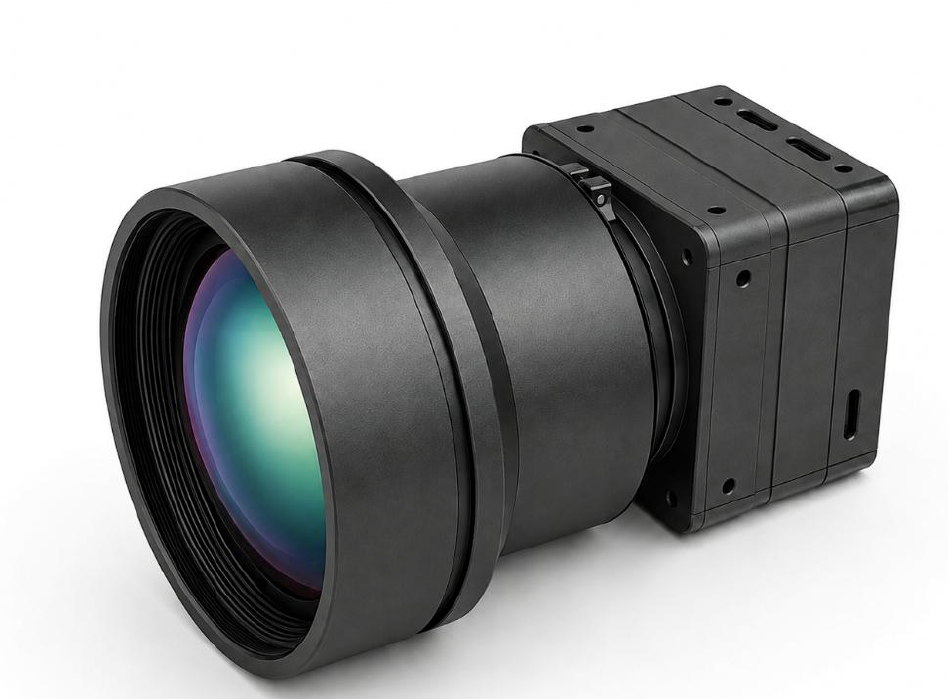
Choosing a thermal camera module for a drone starts with the mission and the airframe—not with the highest number on a datasheet. UAV OEMs need to evaluate the complete payload: module and lens mass, field of view, angular sampling, output interface, power and heat, control requirements, and whether the mission needs temperature data or thermal video only.
The best thermal camera for drone integration is therefore the configuration that meets the required task while staying inside the aircraft’s payload, power, processing, and validation limits. This guide provides a practical selection sequence for OEM teams without assuming that one resolution, lens, or interface is right for every platform.
Key Takeaways
Start with the operational decision. Define what the operator or software must detect, recognize, measure, or record.
Budget the complete payload. Include the lens, housing, connector boards, cables, mounts, and vibration isolation—not only the core.
Evaluate resolution, pixel pitch, and focal length together. Resolution alone does not determine useful range.
Confirm interface and power compatibility early. A suitable image core can still fail integration if the host cannot receive, control, cool, or synchronize it.
Validate with representative data. Bench and flight tests should reproduce the expected target, distance, weather, motion, and display or algorithm workflow.
1. Define the UAV Mission Before Selecting a Module
A useful requirement describes the decision the payload must support. “Thermal inspection” is too broad. A stronger requirement identifies the target, expected distance, minimum anomaly or feature size, required field coverage, platform speed, acceptable latency, environmental conditions, and the output the operator or software must receive.
Mission example | Primary decision | Selection emphasis |
|---|---|---|
Search and rescue | Locate a person or heat anomaly across a search area | Coverage, scene contrast, latency, endurance, and stable imagery |
Utility or solar inspection | Find and, when required, measure an abnormal temperature pattern | Radiometric workflow, calibration, spatial detail, metadata, and repeatability |
Perimeter patrol | Observe and classify activity at a defined standoff distance | Lens and field of view, target sampling, stabilization, and low-light operating workflow |
Mapping or research | Build a traceable dataset for later analysis | Synchronization, timestamps, data format, positioning metadata, and calibration |
Write a testable mission statement
Before comparing modules, record the target dimensions, minimum and maximum working distance, required horizontal and vertical coverage, flight altitude and speed, expected ambient conditions, and the final decision made from the imagery. If temperature measurement is required, also define the expected temperature range, uncertainty target, emissivity workflow, and calibration process.
2. Build a Complete SWaP-C Budget
Size, weight, power, and cost are system-level constraints. A camera core that appears lightweight may require a larger lens, interface board, enclosure, heat spreader, or cable set. The complete assembly also changes the gimbal’s center of gravity and motor demand.
Create a mass roll-up for the module, lens, shutter if used, housing, mounting hardware, connector boards, cables, and vibration isolation. Record dimensions and center-of-gravity coordinates in the same configuration that will fly. Leave margin for manufacturing variation and later design changes.
The power budget should distinguish steady operation from start-up, calibration or shutter events, peak processing load, and any heaters or lens actuators. Heat must have a defined path into the payload structure. A module that operates on the bench can still become unstable inside a sealed gimbal if the thermal path is not representative.
3. Compare Resolution, Pixel Pitch, and Lens as One Optical System
Detector format, pixel pitch, and focal length describe different parts of the imaging system. Pixel pitch and focal length determine angular sampling. Detector dimensions and lens determine the overall field of view. The target size, distance, atmosphere, optical quality, scene contrast, motion, processing, and display then influence whether the resulting detail is usable.
At the same pixel pitch and focal length, a larger array generally provides a wider field of view; it does not automatically place more pixels on the same target. If two systems are designed for the same field of view, the larger array may support finer sampling, but only when the lens and the rest of the imaging chain support it. This is why a resolution label by itself is not a range specification.
For a structured comparison of detector formats, see the thermal camera module resolution guide.
Choose focal length from four inputs
The target’s critical dimension.
The minimum useful pixels or angular detail required by the actual decision process.
The maximum working distance under representative conditions.
The field of view needed to find and track the target.
A longer focal length narrows the field of view and increases target sampling at a given distance, but it can add lens mass and make pointing accuracy more important. A shorter focal length increases coverage but reduces pixels on a distant target. OEM teams should evaluate both acquisition and detail: a narrow view is not helpful if the gimbal or operator cannot reliably find the target.
4. Select the Interface Around the Host System
The preferred output depends on the onboard processor, video transmitter, recorder, autopilot, and control architecture. Do not assume that every interface is available on every module configuration. Request the electrical specification, connector definition, supported video formats, control protocol, latency information, and reference design for the exact unit being evaluated.
Interface category | Potential fit | Questions to verify |
|---|---|---|
Analog video | Legacy transmitters or simple display paths | Resolution, format, digitization stage, noise immunity, and control path |
USB | Prototype, computer, or supported embedded host | Driver support, sustained bandwidth, connector retention, latency, and boot behavior |
MIPI CSI-2 or parallel digital | Compact embedded processing | Lane configuration, voltage levels, timing, raw format, board layout, and driver work |
Network video or data | Distributed payload architectur | Protocol, compression, latency, telemetry, addressing, recovery, and cybersecurity requirements |
For teams evaluating compact embedded links, this overview of MIPI interface considerations can support the first architecture discussion. The selected module’s current interface document remains the controlling source.
Control and synchronization matter too
Video output is only one part of integration. Confirm how the host changes palettes, gain modes, non-uniformity correction, focus, measurement settings, and metadata. Mapping, multi-sensor fusion, and automated inspection may also require timestamps, trigger or synchronization signals, and a documented recovery process after a power or communication interruption.
5. Decide Whether the Mission Needs Radiometric Data
An imaging module provides thermal contrast for observation and navigation. A radiometric system is intended to associate image data with temperature information. The second option is relevant only when the workflow must measure or compare temperatures, and it requires more than a “radiometric” label.
Measurement quality can depend on calibration status, emissivity, reflected apparent temperature, distance, atmospheric conditions, optics, viewing angle, focus, target size, and the software pipeline. Ask how data is encoded, what corrections are applied, which settings must be supplied by the host, and how performance is verified over the required environment.
If the mission only needs situational awareness, adding radiometric complexity may not improve the operational result. If a maintenance decision depends on temperature, rendered color video alone is not an adequate substitute for a documented measurement workflow.
6. Treat DRI as a Planning Model, Not a Guaranteed Range
Detection, recognition, and identification estimates can help compare concepts, but a result is meaningful only when the method is declared. The calculation should state the target dimensions and orientation, the pixel or line-pair convention, focal length, pixel pitch, optical assumptions, atmosphere, target-to-background contrast, processing, display, and probability criterion.
Different DRI conventions use different thresholds. Mixing thresholds from separate methods can produce a confident-looking but misleading answer. For an OEM design review, keep one approved convention and show every input. Then validate the estimate with representative targets and conditions.
Real performance can be reduced by humidity, haze, thermal crossover, vibration, motion blur, focus error, optical transmission, non-uniformity, compression, display scaling, and operator or algorithm behavior. Design margin and flight testing are therefore essential.
7. Use an OEM Validation Checklist Before Design Freeze
Area | Evidence to request | Validation action |
|---|---|---|
Optical | Detector, pixel pitch, lens, F-number, focus method, and field-of-view data | Measure coverage and target detail at representative distances |
Mechanical | Controlled drawing, mass definition, center of gravity, mounting datum, and connector envelope | Install in the intended gimbal and check balance, clearance, and vibration |
Electrical | Voltage range, power states, peaks, pinout, grounding, and protection | Test start-up, brownout, switching events, and full-platform power noise |
Data and control | Format, protocol, driver, latency, metadata, synchronization, and error recovery | Run the real host, recorder, downlink, and control software continuously |
Environmental | Operating limits and applicable test reports | Test the integrated payload across expected temperature, vibration, and airflow |
Supply | Revision control, lifecycle policy, quality process, and change notification | Approve the exact configuration and acceptance criteria for production |
Supplier evaluation should cover evidence and configuration control, not only a headline specification. This OEM thermal camera supplier checklist provides additional questions for technical procurement teams.
8. A Practical Module Selection Sequence
Define the mission, target, distance, coverage, environment, and required decision.
Set complete payload mass, center-of-gravity, volume, power, heat, and cost limits.
Model resolution, pixel pitch, lens, field of view, and target sampling together.
Confirm the exact interface, control, synchronization, latency, and host requirements.
Choose imaging-only or radiometric output based on the operational workflow.
Review drawings and interface documents for the exact proposed configuration.
Run bench, environmental, and flight tests with representative targets and data paths.
Freeze the approved configuration and production acceptance criteria.
FAQ
Does a higher-resolution thermal detector always see farther?
No. Useful range depends on the full optical and operational system, including pixel pitch, focal length, target size, atmosphere, scene contrast, focus, processing, and the detail required by the decision. A larger array may provide wider coverage at the same angular sampling or finer sampling in a differently designed optical system.
What weight should a UAV OEM use for gimbal sizing?
Use the complete flight configuration: core, lens, shutter if present, housing, interface boards, connectors, cables, mounts, and vibration isolation. Include center of gravity and design margin, not only total grams.
Which video interface is best for a drone thermal payload?
There is no universal best interface. The right choice is the one supported by the exact module and the aircraft’s processor, transmitter, recorder, cable length, latency budget, control architecture, and development resources.
When is a radiometric module necessary?
Choose a radiometric workflow when the mission must measure, compare, or report temperature and the full measurement process can be controlled. Thermal video alone may be sufficient when the mission only needs awareness, navigation, or visual localization of heat patterns.
How should an OEM verify DRI range?
Document one calculation method and all assumptions, then test with representative targets, distances, atmosphere, motion, optics, processing, and displays. Treat the calculation as a planning estimate until flight evidence confirms the required probability of success.
Prepare a Technical Evaluation Brief
To evaluate a module efficiently, send VERYTEK the mission, target dimensions, minimum and maximum range, required field of view, platform payload limit, available power rail, preferred interface, host processor, environmental conditions, and whether temperature measurement is required. The next step should be a configuration review followed by datasheet, drawing, sample, and integration testing for the exact proposed unit.